![[Group News] Leaders from Gansu Mobile Paid a Visit for Exchange and Guidance](/d/file/efpub/20250919/5e3579e7820f5f53c8128cbf6290f358.jpg)
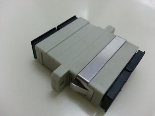
Common technical indicators of optical fiber couplers, such as insertion loss, refer to the dB value of optical loss for each output relative to the input. Its mathematical expression is: Ai = -10lg Pouti/Pin. Optical fiber couplers are also called optical fiber adapters or optical fiber flanges. Optical network systems need to couple, branch, and distribute optical signals, which requires optical fiber couplers to achieve.
Common Technical Indicators of Optical Fiber Couplers
1. Insertion Loss
The insertion loss of an optical fiber coupler refers to the dB value of optical loss for each output relative to the input. Its mathematical expression is: Ai = -10lg Pouti/Pin, where Ai is the insertion loss of the i-th output port; Pouti is the optical power of the i-th output port; and Pin is the optical power of the input port.
2. Additional Loss
Additional loss is defined as the dB value of the loss of the sum of optical powers of all output ports relative to the input optical power. It is worth noting that for optical fiber couplers, additional loss is an indicator reflecting the quality of the device manufacturing process and the inherent loss during device production. The smaller this loss, the better, and it is an assessment indicator for manufacturing quality. Insertion loss, however, only indicates the output power status of each output port, considering not only inherent loss but also the impact of splitting ratio. Therefore, the difference in insertion loss between different optical fiber couplers cannot reflect the quality of device manufacturing. The additional loss of 1*N single-mode standard optical fiber couplers is shown in the following table:
Splitting Ratio: 2, 3, 4, 5, 6, 7, 8, 9, 10, 11, 12, 16
Additional Loss (dB): 0.2, 0.3, 0.4, 0.45, 0.5, 0.55, 0.6, 0.7, 0.8, 0.9, 1.0, 1.2
3. Splitting Ratio
Splitting ratio is defined as the ratio of output powers of each output port of an optical fiber coupler. In system applications, the splitting ratio is determined based on the optical power required by the optical nodes of the actual system (excluding average distribution). The splitting ratio of an optical fiber coupler is related to the wavelength of the transmitted light. For example, when a optical splitter transmits 1.31-micron light, the splitting ratio of the two output ports is 50:50; when transmitting 1.5μm light, it becomes 70:30 (this occurs because optical fiber couplers have a certain bandwidth, i.e., the frequency band width of the optical signal transmitted when the splitting ratio is basically unchanged). Therefore, the wavelength must be specified when customizing optical fiber couplers.
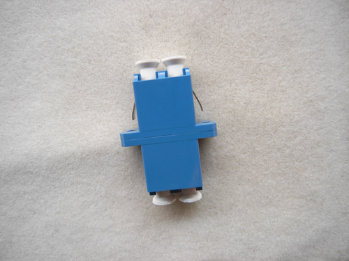
Introduction to Optical Fiber Couplers
1. It is an optical device that realizes the distribution or combination of optical signal power among different optical fibers, constructed by utilizing the mutual exchange of guided wave energy in the adjacent fiber core areas of different optical fiber surfaces.
2. According to the type of optical fiber used, it can be divided into multimode optical fiber couplers, single-mode optical fiber couplers, polarization-maintaining optical fiber couplers, etc.
3. It belongs to the field of passive optical components and is used in telecommunications networks, cable TV networks, subscriber loop systems, and local area networks.
The above is an introduction to "What are the indicators of optical fiber couplers and their meanings?" Please feel free to contact us if you have any related questions.
——END——